|
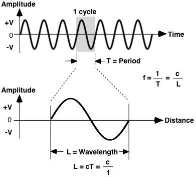
f = c / L T = 1 / f L = c / f = c T |
|
f = frequency L = Wavelength T = period (time to complete 1 cycle) c = speed of light |
|
Calculate Wavelength and Period
Frequency |
| Electromagnetic Wave Parameters |
Electromagnetic Wave Parameters
Parameters that describe electromagnetic waves include frequency, wavelength and period. Frequency is cycles per second (Hertz), wavelength is distance traveled to complete 1 cycle and period is time to complete 1 cycle. The higher the frequency, the shorter the wavelength.
|
f = c / L T = 1 / f L = c / f = c T |
|
f = frequency L = Wavelength T = period (time to complete 1 cycle) c = speed of light |
|
Calculate Wavelength and Period
Frequency |
| Band | Frequency | Period | Wavelength | |
|---|---|---|---|---|
| S | 2.455 GHz | 0.409 ns | 4.83 inch | 12.261 cm |
| X | 10.525 GHz | 0.095 ns | 1.12 inch | 2.848 cm |
| K | 24.15 GHz | 0.041 ns | 0.49 inch | 12.41 cm |
| Ka | 33.4 - 36.0 GHz |
0.030 - 0.028 ns |
0.35 - 0.33 inch |
8.976 - 8.328 cm |
| IR | 333,600 THz | 0.000 003 ns | 0.000 035 inch | 904 nm |
| Source | Frequency | Period | Wavelength | |
|---|---|---|---|---|
| House Current (U.S.) | 60 Hz | 0.0167 sec | 3,105 mi | |
| AM Radio | 530 - 1,700 kHz | 1.89 - 0.589 µs | 1,856 - 579 ft | |
| Citizens Band (CBs) | 26.96 - 27.41 MHz | 37.09 - 36.48 ns | 36.48 - 35.88 ft | |
| FM Radio | 88 - 108 MHz | 11.36 - 9.26 ns | 11.18 - 9.11 ft | |
| DTV | 470 - 806 MHz | 2.13 - 1.24 ns | 25.11 - 14.64 in | |
| Electromagnetic Wave Propagation |
PROPAGATION
Electromagnetic waves consist of an electric field and a magnetic field at right angles to each other. The electric field, E-field, is measured in volts/meter. The magnetic field , H -field, is measured in amperes/meter. The electric and magnetic fields are analogous to voltage and current in circuits. The ratio of electric field to magnetic field in free space is 377 ohms. Power is the vector cross product of the electric and the magnetic fields.
POLARIZATION
Polarization is the plane of the electric field. In the USA over-the-air digital television signals are horizontally polarized while commercial AM and FM broadcast are vertically polarized. Radar waves may be polarized horizontally, vertically, angled, or circular.
Circular polarization is a technique where the electric and magnetic fields rotate at a rate proportional to frequency. Right hand polarization has the fields rotating in a clockwise direction looking from the antenna to the direction of travel, counter clockwise to a target. Left hand circular polarization is just the opposite.
Circular polarization tends to propagate better in rain, but has some signal loss in the polarization process. Circular polarized signals tends to be more reflective for some targets.
| Power Density, ERP, Electric and Magnetic Fields |
Effective Radiated Power, ERP, is the most common unit for measuring signal propagation power. ERP is a function of transmitter power, signal loss to antenna, and antenna gain. ERP equals the product of antenna gain (G) and power delivered to the antenna (Pt/L).
| PERP | = | Effective Radiated Power (watts) |
| Pt | = | transmitter power (watts) |
| G | = | antenna gain (ratio) |
| L | = | transmitter to antenna loss (ratio) |
| Power Density: | Pd = PERP / (4 pi R2 ) | W/m2 |
| Electric Field: | E = (Pd Z)0.5 | V/m |
| Magnetic Field: | H = E / Z | A/m |
| Free Space Impedance: | Z = E / H | ohms |
| R | = | Range (meters) |
| pi | = | 3.1415926... |
| Z | = | 376.73 ohms (Free Space) |
The electromagnetic field is a function of the inverse square (1/R2) of range. Radar signals take a 2-way path, the loss is much greater and a function of the inverse to the fourth power (1/R4) of range.
MEASUREMENTS
Power density and electric and magnetic field strengths measurements must be measured in the antenna Far-Field. The far-field is the range greater than twice the maximum antenna diameter squared divided by wavelength.
|
Rmin = 2 D2 / L
Rmin = Approximate start of Far-Field D = Maximum Antenna Diameter L = Wavelength |
|
Rmin = 0.17 D2 fo
Rmin = Far-Field Range in inches D = Antenna Diameter in inches fo = Frequency in GHz |
| |||||||||||||||||||||||||||||||
Measurements taken in the near-field have absolutely no relation and do not apply to the far-field. Radar manufacturers have a bad habit of listing power densities measured in the near-field, a meaningless number. Just as bad power density measurements are sometimes listed without stating the range of the measurement, another meaningless number.