|
- - - - |
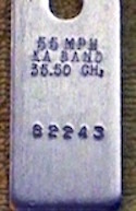
Speed (55 mph) Radar Band (Ka) Frequency (35.5 GHz) Serial Number (82243) |
Police radars should be tested at shift start. Some departments also require testing at shift end. For a dual antenna radar the operator should test each antenna, front and rear, separately.
The Range Control Setting should be adjusted as needed. This setting is actually the receiver sensitivity setting. The Long Range setting is the most sensitive, and may make the radar susceptible to local interference.
The degree a radar self-test and automatically adjust circuits varies with model and ranges from none or little to testing 50 percent or more of the electronics. Self-test only checks and adjusts a portion of the electronics. The radar should also be tested with tuning forks before use.
Radar self-test runs;
|
Tests / Automatic Adjustments may include;
|
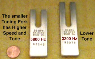
A police or sports microwave Doppler radar will register a speed from a vibrating tuning fork's narrow side, the higher the tone the higher the speed. A radar will also measure a tone from an audio speaker diaphragm. The radar is measuring the microwave reflection of the fork or speaker diaphragm - a complete end-to-end test.
All police radars come with 2 tuning forks (different speeds) tuned for that radar. The forks should be labeled with, Speed, Radar Frequency, and Serial Number for tracking and accountability.
|
|
- - - - |
Speed (55 mph) Radar Band (Ka) Frequency (35.5 GHz) Serial Number (82243) |
Stationary Mode Test
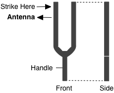
Testing the radar stationary mode is straight forward. Place a vibrating fork a few inches from the front of the antenna, the radar should read the speed the fork is calibrated to induce.
To start the fork vibrating gently strike the top side against a hard object such as wood or plastic, not metal. Once the fork is vibrating place it a few inches in front of the antenna. The fork's "side" must be facing the antenna to register a speed reading. Repeat the test using the other tuning fork.
Moving Mode Test
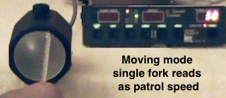
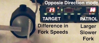
Two tuning forks with different tones are required to test moving mode. One fork simulates the patrol car speed, the other fork simulates a moving target reflection. The moving mode opposite direction traffic test is slightly different from the same-lane traffic test.
| Opposite Direction mode | |
|---|---|
| 1 | Strike both forks |
| 2 | Place SLOWER larger fork in front of the antenna. |
| 3 | Radar should read the fork as PATROL SPEED. |
| 4 | Place FASTER smaller fork in front of the antenna. |
| 5 | Radar should read the speeds DIFFERENCE . |
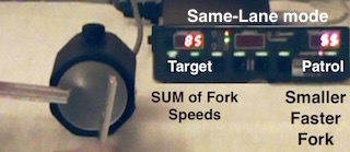
| Same-Lane mode | |
|---|---|
| 1 | Strike both forks |
| 2 | Place FASTER smaller fork in front of the antenna. |
| 3 | Radar should read the fork as PATROL SPEED. |
| 4 | Place SLOWER larger fork in front of the antenna. |
| 5 | Radar should read the speeds SUM . |
| Display | Radar Mode | |
|---|---|---|
| Opposite | Same-Lane | |
| Patrol Speed: Target Speed: |
30 mph 25 mph |
55 mph 85 mph |
Tuning Fork Equations
The tuning fork resonance is equivalent a Doppler shift the radar converts to speed.
The speed reading is based on;
- Radar Frequency
- Tuning Fork Tone (resonance)
|
v = Speed Reading c = Speed of Light |
fd = Fork Tone (Hz) fo = Radar Frequency (Hz) |
|
Calculate Speed Reading
From Radar Frequency and Fork Tone v = c fd / 2 fo | ||
|---|---|---|
| Radar Frequency: | GHz | |
| Tuning Fork Tone: | Hz | |
|
Radar Frequency | ||
|
Calculate Tuning Fork Tone
From Radar Frequency and Speed Displayed fd = 2 v fo / c |
||
|---|---|---|
| Radar Frequency: | GHz | |
| Speed: | ||
|
Tuning Fork Tone | ||
Radar frequency can be estimated from speed and tuning fork resonance. This is an estimate because there is some tolerance in the fork tone, and the equation has inherent rounding errors when calculating transmit frequency.
|
Estimate Radar Frequency
From Fork Tone and Speed Displayed fo = c fd / (2 v) |
||
|---|---|---|
| Tuning Fork Tone: | Hz | |
| Speed: | ||
|
Fork Tone | ||
Periodically (at least once or twice a year) the radar and it's tuning forks should be tested (calibrated) by a certified shop. Testing records should be maintained that include radar and forks tested, dates, test results, and the shop or laboratory that performed the test.
| Radar Calibration Test | ||
|---|---|---|
| • | Radar Make / Model | AMCE Catchem |
| • | Serial Number | XE 04977 |
| • | Transmitter Power | 100 mW |
| • | Transmitter Frequency | 35.5 GHz |
| • | Power Density | 2 mW / cm2 5 cm from lens |
| • | Beamwidth |
12° Horizontal 12° Vertical |
| • | Speed Range |
005 mph min 200 mph max |
| • | Voltage Limits |
10.0 Volts min 16.4 Volts max |
| Tested by: | AMCE | |
| Date: | mm / dd / 20yy | |
| Next Test Due by: | mm / dd / 20yy | |
| Tuning Fork Calibration Certificate | ||
|---|---|---|
| Tuning Fork | Smaller Fork | |
| Serial Number: | 82243 | |
| Resonance: | 5823 | Hz |
| Speed: | 55 | MPH |
| Radar Frequency: | 35.5 | GHz |
| Temperature: | 80 | °F |
| Correction Factor: | 0.02 | MPH/°F |
| Tested by: | AMCE | |
| Date: | mm / dd / 20yy | |
| Next Test Due by: | mm / dd / 20yy | |
| Tuning Fork Calibration Certificate | ||
|---|---|---|
| Tuning Fork | Larger Fork | |
| Serial Number: | 82278 | |
| Resonance: | 3176 | Hz |
| Speed: | 30 | MPH |
| Radar Frequency: | 35.5 | GHz |
| Temperature: | 80 | °F |
| Correction Factor: | 0.02 | MPH/°F |
| Tested by: | AMCE | |
| Date: | mm / dd / 20yy | |
| Next Test Due by: | mm / dd / 20yy | |