| Setup Requirements | ||
|---|---|---|
| Antenna Distance From Traffic Lanes: |
Minimum distance 18 feet Maximum distance 50 feet |
|
| Antenna Height above Ground: | 3 - 6 ft relative to traffic lanes | |
| Camera Alignment: | Set to photograph approaching or receding traffic | |
Operation
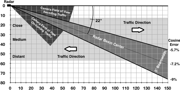
Photo radars are Across-the-Road radars, the beam is pointed across the road instead of Down-the-Road. Across the road radar angles the beam across the road at 20° to 23°.
The antenna must be located such that traffic is within the minimum and maximum design limits. Too close and traffic passes through the beam too fast, too far and reflected signals may be too weak or processing algorithm errors occur. The camera must be aligned for approaching or receding traffic.
| Setup Requirements | ||
|---|---|---|
| Antenna Distance From Traffic Lanes: |
Minimum distance 18 feet Maximum distance 50 feet |
|
| Antenna Height above Ground: | 3 - 6 ft relative to traffic lanes | |
| Camera Alignment: | Set to photograph approaching or receding traffic | |
| Alignment Speed Errors |
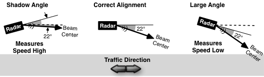
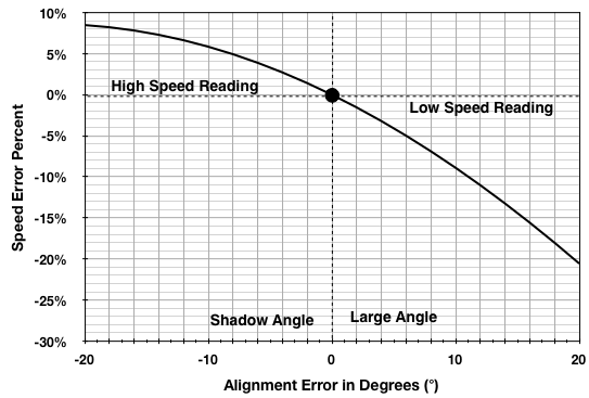
Antenna alignment effects accuracy, pointing into traffic, greater align angle, causes low speed readings and pointing away from traffic, smaller angle, causes high speed readings.
Radar Calculated Speed: vc = vm / cos ß
Radar Measured Speed: vm = vo cos (ß ± ßerr)
|
ß = alignment angle ± ßerr = alignment angle error |
vc = radar calculated speed v = traffic speed |
| Speed Measurement Uncertainty |
Vehicle reflections are not nice clean narrow signals as with down-the-road radar. Across-the-road photo radar reflections are spread out due to alignment angle and the cosine effect.
Measured speed is a function of vehicle speed, alignment angle and beamwidth. Speed measurements are spread, the cosine effect, as an object passes through the angled beam.
|
ß = alignment angle ± ßerr = alignment angle error |
vm = radar calculated speed v = traffic speed |
| Design Alignment |
Close Beam Edge |
Beam Center |
Distant Beam Edge |
Speed Spread |
|---|---|---|---|---|
| 19.5° | -7.3 % | -5.7 % | -4.4 % | 2.91 % |
| 20.0° | -7.6 % | -6.0 % | -4.6 % | 2.98 % |
| 20.5° | -7.9 % | -6.3 % | -4.9 % | 3.06 % |
| 21.0° | -8.3 % | -6.6 % | -5.2 % | 3.13 % |
| 21.5° | -8.6 % | -7.0 % | -5.4 % | 3.20 % |
| 22.0° | -9.0 % | -7.3 % | -5.7 % | 3.27 % |
| 22.5° | -9.4 % | -7.6 % | -6.0 % | 3.34 % |
| 23.0° | -9.7 % | -7.9 % | -6.3 % | 3.41 % |
| 23.5° | -10.1 % | -8.3 % | -6.6 % | 3.48 % |
In reality the reflected spectrum has a greater spread than can be accounted for by the cosine effect and vehicle speed. Empirical data was taken using a radar with a 5° beamwidth angled 20° across the road against a 20 mph vehicle. The cosine effect predicts a spread of 18 - 19 mph, however the data has a spread of 13 - 21 mph. The difference is due to target vehicle wheel rotation adding Doppler reflections.
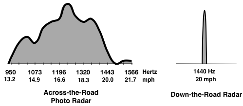
K band radar
20° Alignment, 5° beamwidth
20 mph Target Vehicle
Manufacturers are reluctant to discuss how their radar processes the speed scatter, claim as proprietary information and trade secret. Across the road radars have fractions to a couple of seconds to measure speed. The Cosine Effect error and wheels rotating produce reflections that are not steady stable signals. Across-the-road photo radars are less accurate and less reliable than down-the-road radars.