| vo | = | Actual Speed |
| vm | = | Measured Speed |
| β | = | Cosine Effect Angle |
| R | = | Target Range to Radar |
| d | = | Antenna Distance to Middle of Target Lane |
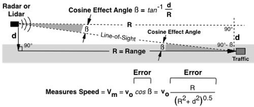
| Cosine Effect Geometry |
|---|
Police microwave and laser radar measures the relative speed a vehicle is approaching or receding the radar. A vehicle traveling directly at or away from the radar measures actual speed, no Cosine Angle Error. Vehicles off angle (off the road) measure speed low. The greater the angle the lower the speed. When the target is near even with the radar the speed reading is 0. This phenomenon is called the Cosine Effect because the measured speed is directly related to the cosine of the angle between the radar and vehicle direction of travel or speed vector. A 20° cosine angle measures speed low by 6%. A 90° angle measures speed as 0 mph.
| vo | = | Actual Speed |
| vm | = | Measured Speed |
| β | = | Cosine Effect Angle |
| R | = | Target Range to Radar |
| d | = | Antenna Distance to Middle of Target Lane |
The antenna pointing angle is completely irrelevant in terms of the Cosine Effect, only the angle to the target vehicle matters.
|
Calculate Measured Speed from Cosine Angle | ||
|---|---|---|
| Actual Speed: | ||
| Cosine Angle: | Degrees | |
|
Actual Speed | ||
|
Calculate Measured Speed from Setup | ||
|---|---|---|
| Actual Speed: | mph | |
| Target Range: | feet | |
| Radar Distance to Lane: | feet | |
|
Actual Speed | ||
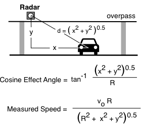
| Overpass |
|---|
The cosine effect has 2 components if the radar or lidar is elevated to traffic such as from an overpass. Radar distance from traffic lane is a function of horizontal and vertical distances.
In the figure, "x" is the horizontal distance to the vehicle lane center, and "y" is the vertical distance to the average top of the target vehicle. Radar distance to vehicle path is "d" and equals the square root of the sum of "x" squared plus "y" squared. If either the horizontal or vertical component is zero, the equations reduce to that shown above.
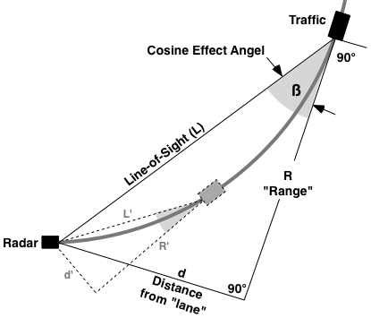
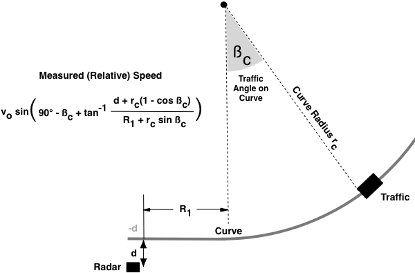
| Traffic on a Curve |
|---|
The cosine effect angle on curves is large and changing proportional to curve radius and vehicle speed. The relatively large and fast changing cosine effect angle results in measured speed changing relatively fast, too fast in most scenarios for a radar or lidar to measure speed.
Microwave and laser radars cannot measure traffic speed on a curve because the angle is changing causing the relative speed to change too fast for the radar or lidar to measure.
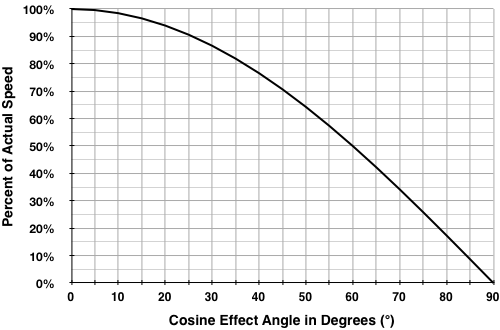
| Cosine Error Graph |
|---|
The below figure is a graphical representation of the Cosine Effect for measured speed as a percentage of true speed versus angle. The larger the angle the larger the error and the lower the relative target speed. At angles of only a few degrees the speed is 99% to 100% of actual, at an angle of 60° the speed is half actual speed. At 90° speed is 0 relative to the radar or lidar.