Home
Radar Components
Page Outline
Radar Block Diagram
Basic hardware is similar in most radar models. Differences do exist; some models are for stationary use only, and some are for both stationary and moving mode. Some models are single units, and some are two or more pieces (boxes) and/or have multiple antennas. Many units measure only approaching targets; others measure both approaching and receding targets. Some moving mode radars have the ability to measure same-lane (direction) traffic (front and/or rear of patrol car). The below figure represents a typical system for traffic radar. For multi-piece radars the antenna is usually separate from the rest of the electronics.
Figure D-1 --
Radar Block Diagram
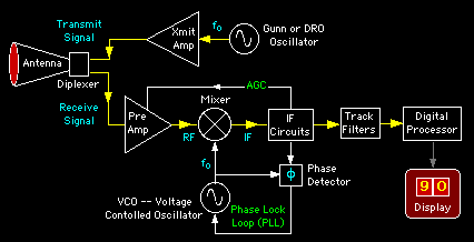
Antenna
GAIN
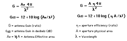
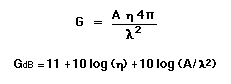
Antenna gain (G) can be expressed in terms of wavelength (Lambda) and effective antenna area (Ae). Effective antenna area is physical area (A) times efficiency (Eta).
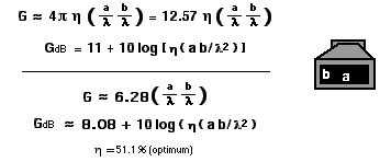
Efficiency for a pyramidal horn antenna is typically 51.1 percent (optimum), but can be as great as 80 percent (a very long flare length). Gain for an optimum pyramidal horn can be estimated from aperture horizontal and vertical dimensions (a and b). Note the product of a and b (a x b) is area.
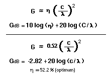
Optimum gain for a conical horn can be estimated from aperture circumference (C), wavelength, and efficiency (typically 52.2%).
Gain for a parabolic reflector can be estimated from the plane circular area (A) the reflector covers. Note antenna efficiency is typically 50 to 65 percent.
FAR-FIELD
Antenna gain and beamwidth are antenna (pattern) parameters that apply only at long ranges. Long ranges are defined as any range that is greater than two times the diameter squared of the radar antenna diameter divided by the wavelength (see below figure).
Figure D-2 --
Antenna Far-field Region
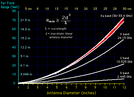
The Fresnel region is defined as the range that is less than the far-field and greater than half the range of the minimum far field. The range less than half the distance of the far-field is the near-field region. In the Fresnel and near-field regions the beam is still forming (focusing).
Diplexer
An important component associated with a shared transmit/receive antenna is the diplexer. A diplexer is a passive device that routes the transmit signal to the antenna and not the receiver, and routes signals from the antenna to the receiver and not the transmitter. The diplexer is not perfect and leaks signals to other ports, but leakage is greatly attenuated if the device is designed properly. However, some transmitter leakage is required for use by the receiver in order to fine-tune (with a PLL -- phase-locked loop) the receiver VCO (Voltage Controlled Oscillator) to compensate for any transmit oscillator frequency drift.
Transmitter
A Gunn (diode) oscillator or a DRO (dielectric resonant oscillator) can be used to generate the radar microwave transmit signal. A Gunn oscillator is a solid-state device and a DRO is a ceramic device. An amplifier may be required to increase signal power before transmission with either device. DROs are less stable (in frequency) and seldom used as a transmit signal source.
Phase-Lock Loop (PLL)
Traffic radar is designed to detect transmitter leakage to track any frequency drift of the Gunn or DRO oscillator. If the transmit frequency drifts, the receiver electronically tracks this drift with a phase-lock loop (PLL) and tunes the receiver to the proper frequency by adjusting the VCO (voltage controlled oscillator) frequency.
Receiver
The AGC (automatic gain control) circuits adjust receiver gain (sensitivity) to prevent receiver saturation from strong signals, such as strong ground echoes or large close targets. However when the AGC lowers the receiver gain, targets at longer ranges and/or smaller targets may not be detected.
Target return signals are enhanced by a low noise amplifier (LNA). This amplifier differs from the transmit amplifier in that the transmit amplifier is intended to boost a signal of moderate power as much as possible (noise gets amplified too) while the LNA is intended to enhance a weak signal without amplifying or adding noise.
After the LNA processes the signal a mixer down converts the signal to an intermediate frequency (IF). The IF is the difference between the target return frequency and the local oscillator frequency. Some moving-mode radars adjust the local oscillator frequency proportionally to the patrol car velocity in order to subtract the radar's velocity (patrol car speed) from target returns. This allows the same IF circuits and track filters to process both stationary and moving modes.
Processing
The IF circuits process signal returns for use by the track filters. The track filters separate the returns to detect discrete signals for power and frequency. Any signals detected are sampled and tracked by a digital processor. If multiple targets are present, the processor determines which ONE (or two) to display. Microwave radars update the display approximately one to four times per second depending on model. Radar integration time (sample time period) is equal to or greater than (whole number multiple) of display update time.
CopRadar.com
Radar Components
Home