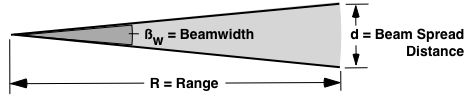
d = 2 R tan(ßw / 2)
d = beam spread distance, R = range, ßw = beamwidth
Calculate Beam Spread (d)
| |||||||||
| Beamwidth |
Antenna beamwidth limits radar ability to distinguish multiple vehicles. When several vehicles are in the beam the operator must interpret, sometime guess, which vehicle the radar is tracking.
Beamwidth varies with model from about 9° to 25°, the larger the antenna and the higher the frequency the more narrow the beam. Circular antennas have a symmetrical beam, the same beamwidth in the vertical and horizontal planes. Rectangular and elliptical antennas have a more narrow beamwidth in the plane the antenna is wider, and a wider beamwidth where the antenna is more narrow.
| |||||||||
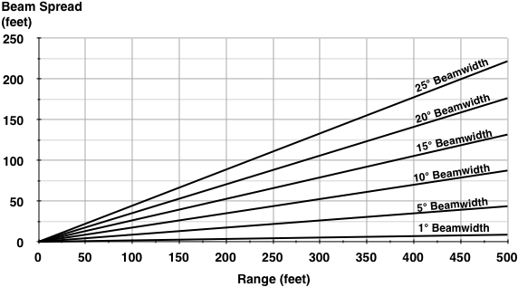
The figure below graphs beamwidth spread in feet versus range for a beamwidth of 1, 5, 10, 15, 20, 25, and 30 degrees. Most police down the road radars have beams between 9° and 15° that easily covers several lanes of traffic at relatively short ranges.
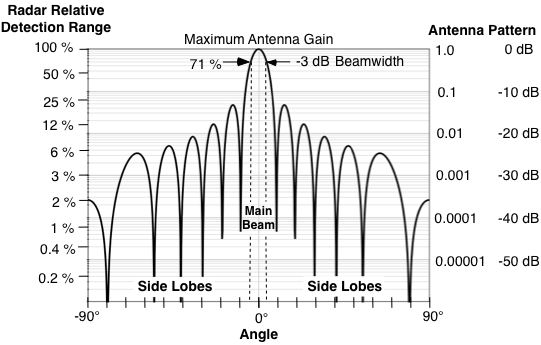
Antenna beamwidth is defined as the angle between the half power, -3 dB, points. A radar has maximum detection performance in the beam center. At the beam edge, -3 dB point, radar detection range decreases 29%. Detection capability drops dramatically past the beam edges, but not to zero. Antennas have some detection capability outside the main beam in the antenna side lobes.
| Beam Detection Pattern |
Radar has maximum detection range at the center of the beam. At the beam edges detection is down to 71% (-29%) compared to beam center. The vertical axis on the below chart is on a log scale for better resolution. The side lobes get a littler wider with lower magnitude as angle increases. The back lobes are unpredictable but still large enough for some detection capability.
|
d = antenna diameter L = wavelength pi = 3.14159 |
ß = angle off boresight n = antenna efficiency |
Beam Masking
At microwave frequencies signal transmission and reflections are of a line-of-sight nature and do not bend or fringe around objects as do commercial AM and FM radio waves. Reflective objects mask and reflect radar signals, large non reflective obstructions can absorb and disperse signal energy.
Mask and Reflect
|
Reflect
|
Mask
|
Antenna Equations
At microwave frequencies signal transmission and reflections are of a line-of-sight nature and do not bend or fringe around objects as do commercial AM and FM radio waves. Reflective objects mask and reflect radar signals, large non reflective obstructions can absorb and disperse signal energy.
|
G = Gain A = Antenna Area |
L = Wavelength n = Antenna Efficiency c = Speed of Light |
|
ßw = Beamwidth in radians d = Antenna Diameter |
fo = Frequency c = Speed of Light |
|
fo = Frequency in GHz d = Antenna Diameter in inches |